Related Articles

A post after a long time !
I have done some considerable amount of work on my Arduino since I purchased it. Worked with PhotoResistors aka Light Sensors, PIR Motion Sensors, LDR Temperature Sensors etc. And I must say, it’s fun playing around with sensors.
So here’s a small and easy tutorial for controlling LEDs using IR Remote Contol.
Things Required :
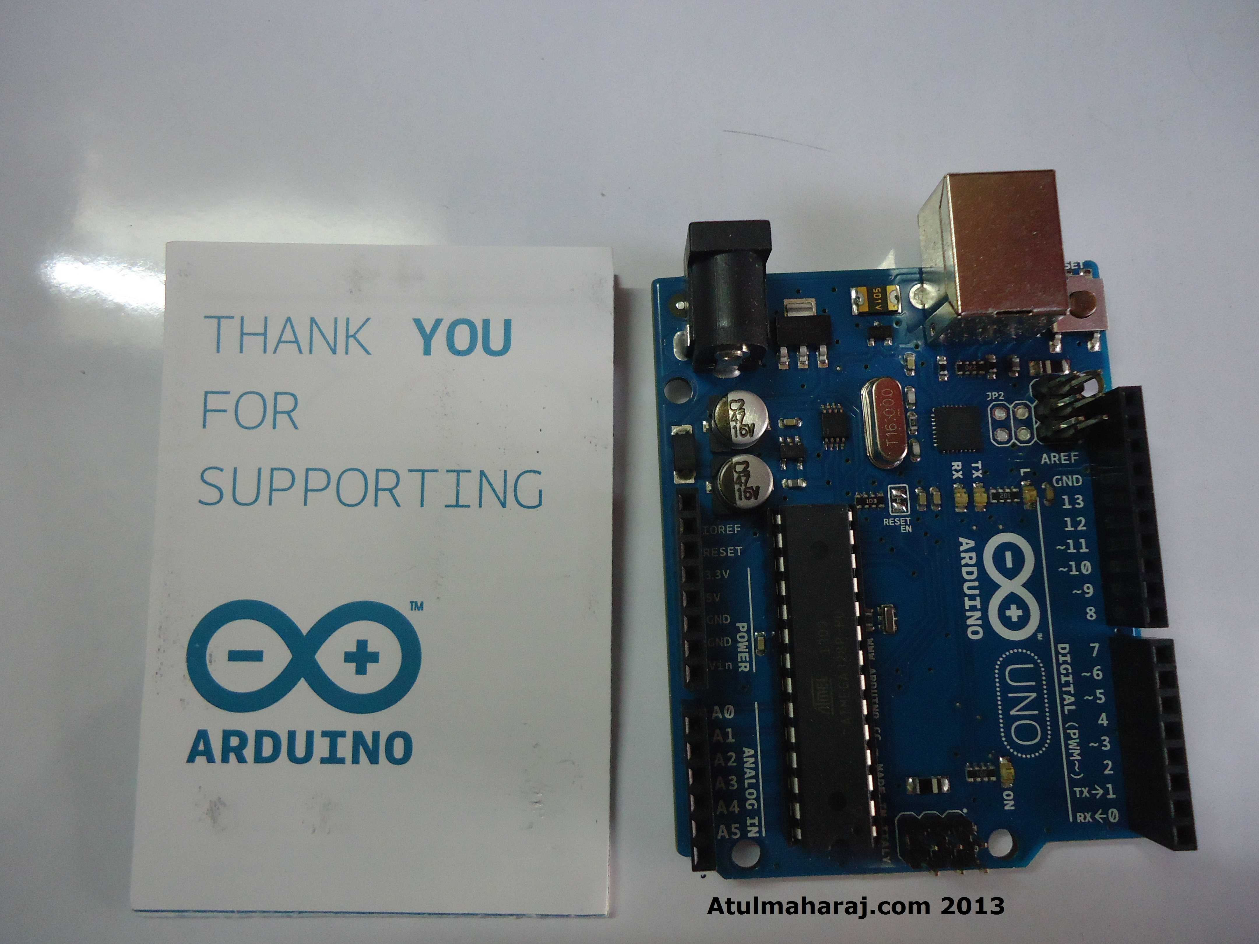
- Arduino Board
- TSOP 1738 IR Receiver. (Purchase online)
- Remote Control (Any TV Remote would do)
- LEDs
- Patch Wires
To start with, grab the TSOP 1738 IR Receiver, this works on active low principle i.e. its output remains high but becomes low on some input. The TSOP 1738 is a 3 pin device. Keeping the bulgded portion facing you, the leftmost pin is Ground, Middle pin is Vs (5 V) and the rightmost pin is Output.

To run this program you will need the IRremote.h header file. (Download Here). Once downloaded, extract the .zip file and rename it to IRremote. Now place this folder in libraries folder in your arduino directory.
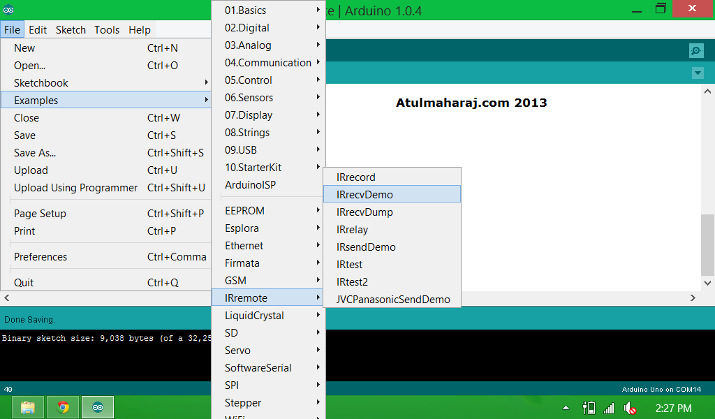
Once this is done, start the Arduino IDE. Goto File->Examples->IRremote->IRrecvDemo. (Check the picture below)
Now burn the program to the board. Start the Serial Monitor (Crtl+Shift+M). Point the tv remote to the IR Receiver and press any button, note the corresponding values shown in the Serial Monitor.
Now moving on with the example, place the LEDs on the bread board and connect them to your arduino(Red->pin 4, Green->pin 7, Yellow-> pin 8) and to ground.
See the code below :
[code language=”c”]#include <IRremote.h> //Include the IRremote.h file
int RECV_PIN = 2; //TSOP 1738’s Out pin
int red = 4;
int gre = 7;
int yel = 8;
IRrecv irrecv(RECV_PIN);
decode_results results;
void setup()
{
Serial.begin(9600);
irrecv.enableIRIn(); // Start the receiver
pinMode(red, OUTPUT);
pinMode(yel, OUTPUT);
pinMode(gre, OUTPUT);
}
void loop() {
if (irrecv.decode(&results))
{
if(results.value==2080 || results.value==32) //Compare received values from Remote
{
digitalWrite(red, HIGH);
digitalWrite(yel, LOW);
digitalWrite(gre, LOW);
}
else if(results.value==2064 || results.value==16)
{
digitalWrite(red, LOW);
digitalWrite(yel, LOW);
digitalWrite(gre, HIGH);
}
else if(results.value==2065 || results.value==17 )
{
digitalWrite(red, LOW);
digitalWrite(yel, HIGH);
digitalWrite(gre, LOW);
}
Serial.println(results.value);
irrecv.resume(); // Receive the next value
}
}
Burn the above code and run the program. Point the remote to the receiver and press the volume(+) ,volume(-) and channel(+) keys to see the different LEDs being illuminated ! (the values are based on the remote I am using, you might receive different values from your remote)
Checkout the video below for demo –
Voila !! You have create remote controlled LEDs !
This is one of the simplest and the easiest sketches. Hope this helped you. For any information, feel free to contact !